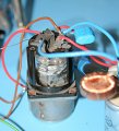
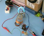
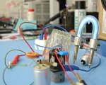
I wounded secondary coil on a tea glass (7cm top diameter) with 52 turns of 0,35mm enameled wire from an old dismantled transformer. I decided to omit primary coil and use bottom-feeding method. So problem with primary circuit tuning and searching for suitable HV HF capacitor disappeared. In this case the tube is quite weakly loaded with high impedance of TC resonator and there's no serious danger of tube overload. The main drawback of this circuit is direct connection to mains power. This means that touching parts of the circuit and TC output can be lethal. So I don't recommend to follow this description by beginners. The whole TC was built in roughly one hour.
The circuit is very minimalist. Mains voltage is half-wave rectified by the diode and blocked with small capacitor. Capacity is too low to smooth the DC voltage so tube can relax every half of period and average power is lower. DC voltage is fed to plate via RF blocking choke. I used 470 µH (could be larger) on ferrite toroid core. It directs the RF current to flow into TC resonator and not back to mains. When TC resonator is driven at its own resonant frequency the impedance will drop and it will draw the highest RF current from plate. The grid is driven by feedback coil made of 7 turns at 5cm cylindrical form (form was removed after fixing windings by hot glue). First I had tried an antenna feedback but it didn't start to oscillate. I reached the best result with quite weak feedback coil coupling. When it was tight oscillations often dropped out. This is why feedback coil is laying under the glass partially outside. In this setup the oscillations will start reliably even when loaded/unloaded by bulb as a plasmaglobe. I measured that it is oscillating at ~3,7 MHz. I expected higher frequency for such low turns count.

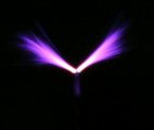
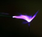
I used 60W bulb as a current limiter in series with circuit for initial testing. Once it was well tuned I connected it directly to mains. It survived roughly 15 minutes operation without any failure and overheating for the pleasure of spectators. It makes 1 cm long sparks to metal objects and can light glowing tube at 20 cm distance. It cannot be compared with my other Tesla coils but it made a good job and I tried bottom-feeding method. I would like to try this with some of my regular TC secondary. UPDATE: I tried this circuit with 3 of my existing secondaries but performance was very poor. It could only light a small glowing tube or do sparks up to 1 mm long to grounded object. I can notice that bigger secondaries performed worse. On such low frequencies the impedance of bottom feeded secondary is simply too high compared to tube which cannot drive it effectively. Usually this circuit drives VTTC in frequency range around 10 - 50 MHz, one similar circuit is here.
 |
 |
 |
 |
 |
 |
 |
 |
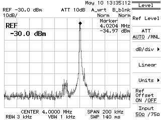
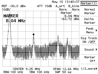
10.5.2010 We got new spectrum analyser Advantest R3131 at work today and I had some free time to play with it. So I tried to measure the RF spectrum of this TC (from 3m distance, a piece of wire as antenna). On the left image you can see the fundamental frequency f0 = 4,0204 MHz (spectrum width is 200 kHz). On the right image is much wider spectrum including the 2nd and 3rd harmonics (the last on the right side is from ambient noise). The 2nd harmonic power level is about 30 dBm below the f0.
 |
 |