 |
 |
 |
inductor II
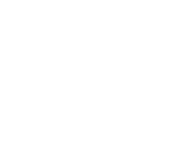
17.7.2007 After a long time I returned back to my old ignition coil inductor. I decided to try a new solid-state driver circuit with power MOSFET. It could work more efficient and safe (because of lower supply voltage insulated from mains). The circuit is based on popular timer NE555 which works as an astable multivibrator. The Frequency and duty cycle of generated rectangular waveform can be adjusted by two potentiometers in range around 10 - 800 Hz. Because of duty cycle on 555 output vary in range 50 - 100 %, there is a bipolar transistor invertor to revert duty cycle into range 0 - 50 % (we don't want to saturate coil's core too much). For switching the coil I used some MOSFET which was laying handy (probably smaller one could be used as well). Basic ratings of IRFP460 are 500 V / 20 A / 280 W / 0,27 Ω Rdson. MOSFET is protected against high voltage spikes by a transil across D-S and 20V Zener diode across G-S against HV spikes transfered through Miller capacitance from drain to gate. Later I found out that IRFP460 is 100% avalanche rated so it will clamp D-S voltage near over 500 V itself without any damage and transil is then not needed. The heatsink doesn't get hot. The power supply is made of common double-rectified 24VAC transformer (from an old VCR). To prevent breaking of transformer's primary-secondary insulation when sparking to random grouned objects I connected the common terminal of ignition coil (+ supply rail) to mains ground (PE).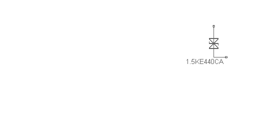
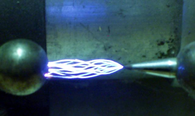
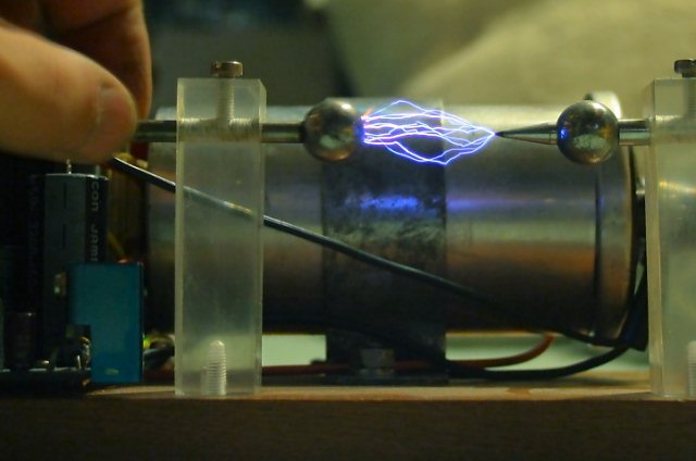
At the beginning I played with the circuit on universal connection pin array and later I made simple PCB. It worked at first turn on. I also made a new nicer baseboard and robust discharge electrode holders from acrylic glass (the older ones from pen tubes was ugly). First I tested how much supply voltage the coil can withstand. At 50 VDC it made great sparks up to 5 cm but during a short time it suddenly disappeared and something had started to smell. I considered that coil secondary has broken so it was trashed... Unfortunately I didn't take any photos yet.
22.8.2007 I obtained another ignition coil (PAL Magneton rated for 12 V) which I handle more careful now. Power supply delivers 30 V peak after rectifying to coil making sparks about 3 - 4 cm long. The spark length depends on frequency and duty cycle setting. At higher bangrate and duty cycle discrete sparks become in to continuous hot buzzing arc which is capable to burn various things.
 |
 |
 |
 |
14.3.2010 One colleague at work brought to me a lawnmower ignition coil for my experiments. It is much smaller compared to classic car ignition coil - about 5 cm in diameter and 2 cm height. I got it without core so I tried to improvise something. I dismantled a color TV IHVT to get its ferrite core. The core pillar fitted in the hole nicely but pillars spacing were about 3 mm less than needed. So I had to crack the core and use only L-shaped part. Here I present measurement of windings parameters compared to classic car ignition coil (transformation ratio was calculated according this equation: N1/N2 = sqrt(L1/L2)):
| coil | Rpri | Rsec | Lpri | Lsec | ratio |
|---|---|---|---|---|---|
| car ignition coil BN202B Magneti Marelli | 3,2 Ω | 7,2 kΩ | 12,4 mH | 56 H | 1:67 |
| lawnmower ignition coil without core | 0,2 Ω | 2,7 kΩ | 116 µH | 0,87 H | 1:86 |
| lawnmower ignition coil with "core" | 0,2 Ω | 2,7 kΩ | 0,4 mH | 1,55 H | 1:62 |
You can see that transformation ratio is very similar but primary resistance and inductances are much smaller. It's due to thicker wire and less turns at primary and using ferrite instead of iron. We had cut one smaller coil to insight. Secondary winding is made of a hair-thick wire wound on a plastic form into insulated sections. All is well impregnated by epoxy to improve the insulation. I connected the coil to my inductor MOSFET driver and set it at higher frequency. It can make 2cm sparks and up to 3cm arc can be pulled out. The coil survived my experiment without breaking. I think it's not bad output for such small coil...
 |
 |
 |
 |