 |
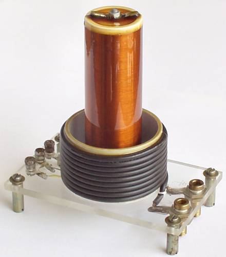
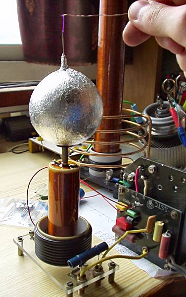
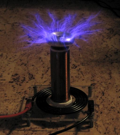
The secondary coil resonant frequency is about 4,5 MHz without add-on capacity. This is quite high frequency. First I tried to use my SSTC driver with SU169. The circuit started oscillating but transistor was operating up its limit and the spark was poor. I pulled out arc about 1 cm only. So I wasn't satisfied with it. VTTC power supply is still under construction so I tried classic sparkgap driver. I took 5 kV / 120 VA neon sign transformer, two parallel wired disc impulse capacitors 1 nF / 15 kVAC and old sparkgap made of copper pipes which I modified for lower voltage. On the top of the secondary coil I put discharge electrode made of alufoil coated tennis ball with a needle on top. After I turned it on I saw great sparks. It was jumping from the needle spike and there was a corona around top turns of secondary winding too - this is not good. I should try to use torus shaped discharge electrode but I have not a proper skeleton. When I put fluorescent tube closer I saw about 7 cm long sparks. But the sparkgap became hot in few minutes and it's function was going wrong and sparks was contracted to 4 cm. I should use robust copper pipes with fan heat and ion spreader.
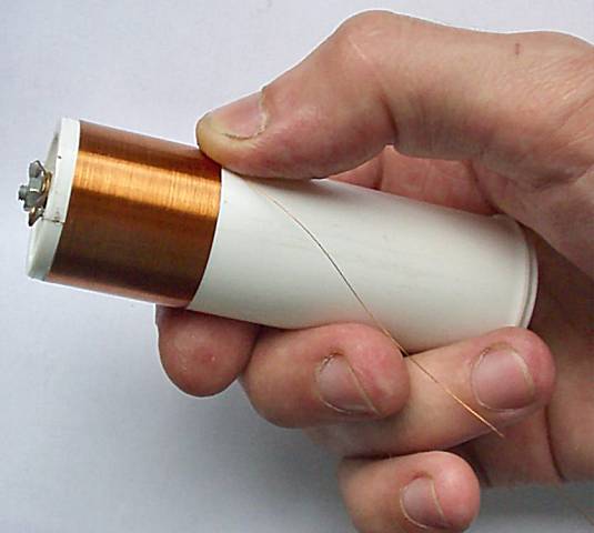
So I was surprised with my minitc's power. I will make some tunings and it will be perfect. I thing its efficiency is quite good - 7cm sparks / 120 W input power. It's probably result of good tune by 2nF capacitor which is enough (but not enough for big TC). I'm afraid of applying more input power. I will not damage secondary coil by corona and turn-to-turn shoot-throughts. The device is small and there's no problem to put it into case and go somewhere to make a show ;-)
 |
 |
 |
 |
 |
 |
|
29.8.2002 So my miniTC was burned today
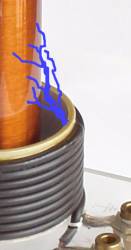
:-(((. When I was trying to increase sparking by more load breakdown was happened. There was a spark shoot-throught
between top primary turn and secondary coil surface (signed on picture). And there was inner sparking in the tube too.
Because secondary coil was burned in some places on the surface it became useless (damned, several hours of work lost).
So I'll wound a new one. I have to do whole reconstruction of miniTC and correct some construction mistakes which I had made. 1) I unwound primary coil and removed feedback coil for VTTC driver. There was induced too high voltage in it and it sparked on its terminals (14 turns only). 2) I had to shorten wire of primary coil because its insulation was burned in fold. This mean decreasing number of primary turns to 8. Then I wound back the wire but I didn't put it through PVC pipe. Instead I lead it down on outer side of the pipe. 3) In this evening I wound a new secondary coil on another tube. I didn't drill any holes for wire through the tube this time. Now I fixed the wire by micro solder-iron - I melted it into the tube surface but not get it through. A screw on top was melted into thick plastic pad and glued on. 4) The cap of the tube, which was fixed by screw to plexiglass base, was trashed. Instead I glued another one there. I will varnish the coils tomorrow. So I hope that presented modifications increase an electrical solidity of the device and next experiments will success. |
 |
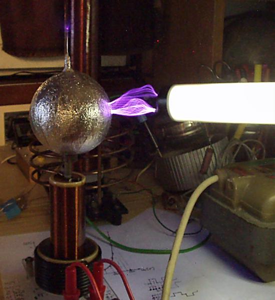
19.12.2003 MiniTC lay in cabinet for a long time. Now I've got a small toroid recessed from aluminium by Thomas. So the time for the next ignition has come. I smoothed the toroid and add screw thread. The circuit was the same like before - 5kV NST, copper pipe sparkgap and 2 nF capacity. NST was now powered by variac to prevent miniTC damage.
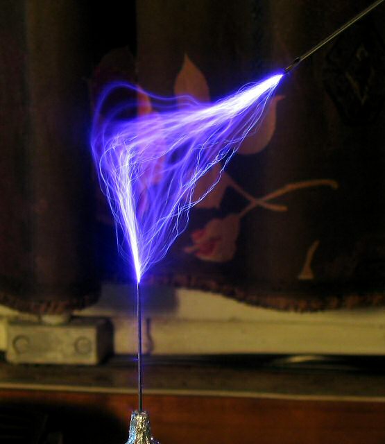
Spark streamers reached up to 8 cm to ground wire. When I didn't place any discharge point on the toroid strong primary to secondary flashovers occured. Fortunately acrylic enamel on secondary was more resistant than resin used before and any damages didn't happen. Probably the best solution would be to rewound primary to a flat or conical spiral. But I'm too lazy to redesign miniTC primary and base (secondary is glued). I'll try to extend primary form with some piece of pipe...
 |
 |
 |
 |
 |
23.12.2003 As a protection against the flashovers I glued another 18 mm piece of pipe on current primary form. This almost eliminated primary-secondary flashovers but 'racing sparks' rised on secondary winding surface. Simply sometimes a spark jump from some secondary turn and travel higher along the secondary winding and then jump back to another turn. Colleague Liviu suggested me that this is due to overcoupling between the primary and secondary coils (the magnetic field is somehow confined in a little place between the two coils). When I calculated the coupling by MANDK software it gives me k = 0,2975. I was initially relied on SSTC / VTTC driving (higher coupling is better) but it was not approved. So I tried to make a temporary flat spiral primary coil. I estimated the parameters (d1 = 50 mm, d2 = 100 mm, N = 5,5 turns), coupling ~ 0,13. There was a surprise for me while I turned it on - the flashovers and racing sparks has gone. Now sparks jump to sides and up from the toroid. So I disassembled my miniTC and tomorrow I'll work on new base and primary. In this occasion I remeasured secondary resonant frequency. It is 2,47 MHz without toroid and 2,17 MHz with toroid.
 |
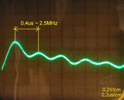 |
| temporary flat spiral | transient response |
miniTC II
 |
1.1.2003 I completely disassembled my old miniTC. I had to revarnish the secondary because I partially clean off the old varnish by spirit. I cut-off new bigger base from plexiglass drilled holes and mounted foots and banana jacks. I had no experiences with winding a flat spiral coil. Maybe it could be done by winding a solenoid and then stretch out and flatten it. But I did it other way. I cut off thin piece (little bit more than wire diameter) of thick-walled plastic water pipe and I drilled a hole into it and trapped one end of wire into this hole. I gripped it between two boards so there was only a crevice for wire and wound on about 6 turns. But when I released the wire it lost a form little bit. So I reclaimed this snakes-glomerule by thin fishing line which keeps the turns tight on right place at the base. The ends of wire are threaded through to bottom base side and soldered to banana jacks. According to calculation I used 4,6 primary turns. Details of windings are here.
Now there are no flashovers during operation. But it seems to me that sparks are less bright than before. I'll need to add some primary capacitance because sparking bring down the secondary fres. It would need to little 'undertune' the primary circuit. When I get some piece of robust copper pipe I'll make a new sparkgap because the current sparkgap overheats in few minutes of operation.
 |
 |
 |
 |
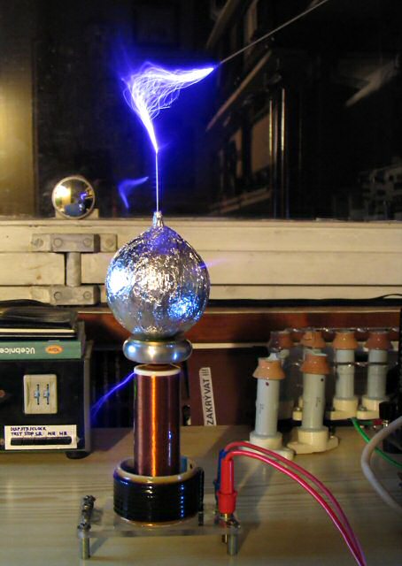
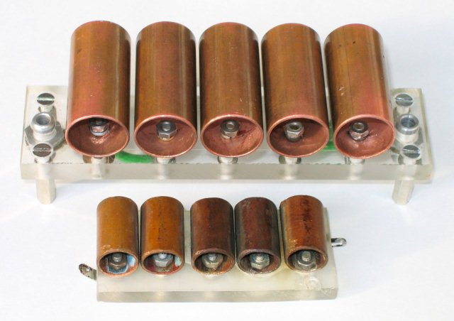
16.9.2006 The original sparkgap I had used was made quickly for testing but had quite bad performance. It overheated in a minute and hot copper pipes started to melt plexiglass base. When I later get some piece of 18 mm diameter copper pipe (of course it could be more) and had some free time, I made new sparkgap. There are both sparkgaps on 1st picture below for comparison. Design is the same but bigger. I planned to make about 0,5 mm gaps but when I made it was a little bit more. On 2nd picture we can see a complete circuit in full splendor of simplicity: TC, sparkgap, tank capacitors and 5 kV / 120 VA NST-XFMR. Now it can operate several minutes without significant power fade out.
 |
 |
 |
 |
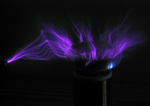
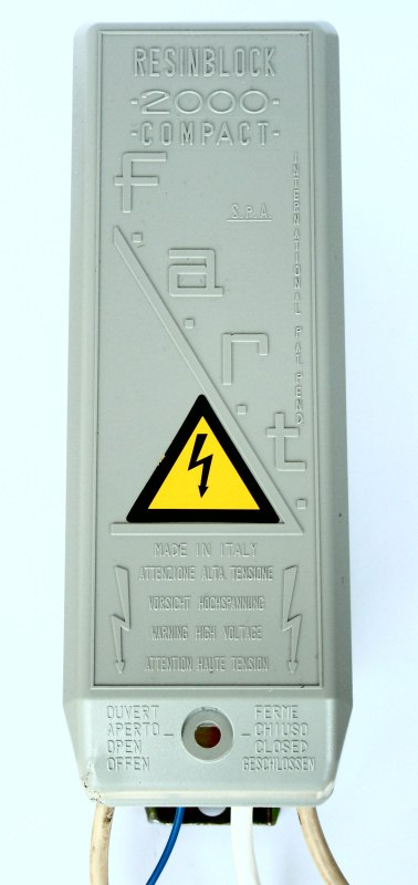
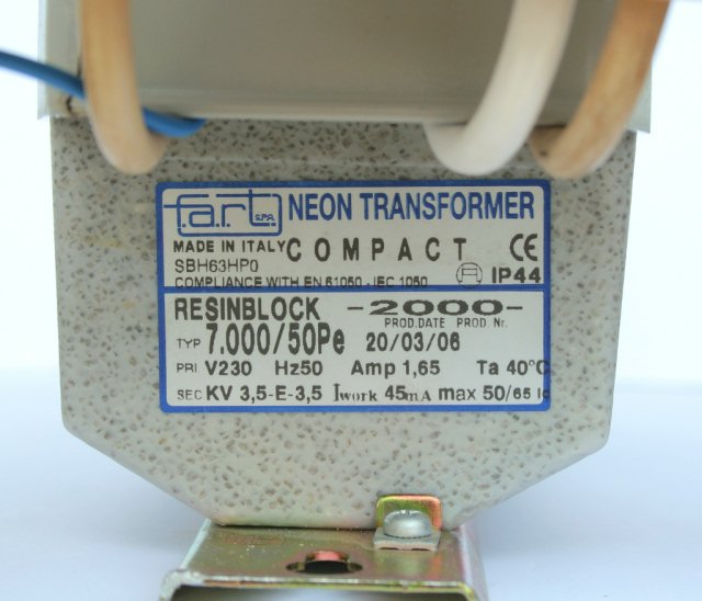
1.6.2008 During the reconstruction of our company building there were also neon sign tubes replaced by modern, more effective, LED backlight and I got one neon sign transformer. It is a 230 V / 1,65 A to 2 x 3,5 kV / 45 mA (with common node) NST made in Italy by f.a.r.t. (not a fart :). It's compound-insulated NST and weights 6 kg. So I got ideal power supply for my SGTC. I connected it (both secondary windings - 7 kV) to SGTC and opened all gaps on the spark gap. I turned it on and a loud noise appeared. Sparks was significantly greater. But sometimes a spark jumped over safety sparkgap (10mm gap) on capacitor bank making very loud bang so I had to disable one gap to little lower the voltage. Also BPM has raised up. Then I can touch the sparks with screwdriver or fluorescent tube without several shocking. Now the sparkgap heats a lot so I will need to make some active cooling with a fan...
 |
 |
 |
 |
 |