 |
 |
 |
 |
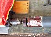
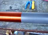
At the first time it doesn't wind too easily and after few tens of turns wire jumped out of the track. It means that I must stop and unwound some turns back and start again. But after 1/3 of winding I got it in my hands and wounded remaining 2/3 quickly. All winding takes me about 3/4 hour. Then I started with varnishing. I didn't used resin in alcohol after my previous problems but I bought an acrylic (clear) paint spray. I sprayed on the winding with multiple layers to get it thick enough. It was not cheap but there's a lot of advantages - fast drying, higher mechanical and chemical resistance...
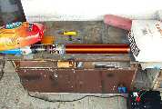
At the beginning I was planning to use this TC with SSTC/VTTC driver only. This mean that I need great primary to secondary coupling. So I wounded primary coil on 11,2 cm PVC pipe with 13,75 turns. After my previous experiences with curving a thick copper wire (which is overdesigned for my small TC but looks cool ;-) I decided to choose something thinner-insulated 2mm wire. I tried to make some spacing to prevent turn to turn touching. At the bottom of pipe I wounded feedback coil with 16 turns and 2-trun and 8-turn taps. Here are winding data details. I varnished primary coil to fix the wire too. The bottom base is made of plexiglass (my favorite material). And here are all my TCs:
 |
17.7.2003 Tuning: I didn't calculate fres first (later I calculated that it should be ~370 kHz). My estimation was around 0,5 MHz. To do needed calculations easier I wrote a simple electro & TC calculator in PHP. Now it's time to measure it. I thought that connecting to my working bipolar transistor flyback would be the easiest way. Then I would read frequency of generated elmag. field on my frequency counter. But that was a mistake. For some reason the flyback driver oscillate somewhere around 800 kHz. After swapping feedback coil terminals it changed to about 320 kHz. And then let's make a choice. In both cases the sparks was very poor-worse than with old TC.
 When I have started to study causes of this effect I discovered that Tesla Coil is more
complex device than I had thought. For measuring fres is needed to connect source of driving signal to the base of
secondary coil via serial resistor, (other generator terminal must be grounded) and leave secondary top free in air as
shown in right side schematics. This mean don't connect generator directly to both end of the coil. Secondary coil is
not insulated system but it's capacitive coupled to surroundings. Sine wave generator is useful for this measurement
but 50% duty cycle square wave TTL generator may be used too. Problem of square wave signal is that its spectrum contains
a lot of odd harmonics. Then it may happen that our TC with fres=300 kHz is excited not only by 300 kHz square
wave signal but 100 kHz too due to 3rd harmonic.
When I have started to study causes of this effect I discovered that Tesla Coil is more
complex device than I had thought. For measuring fres is needed to connect source of driving signal to the base of
secondary coil via serial resistor, (other generator terminal must be grounded) and leave secondary top free in air as
shown in right side schematics. This mean don't connect generator directly to both end of the coil. Secondary coil is
not insulated system but it's capacitive coupled to surroundings. Sine wave generator is useful for this measurement
but 50% duty cycle square wave TTL generator may be used too. Problem of square wave signal is that its spectrum contains
a lot of odd harmonics. Then it may happen that our TC with fres=300 kHz is excited not only by 300 kHz square
wave signal but 100 kHz too due to 3rd harmonic.For coarse estimation of fres we only need some square wave generator with sharp edges (duty cycle is not important). We set few kHz or tens of kHz at the generator and watching for signal edges on oscilloscope. A ringing should be seen at rising and falling edges of square wave. We estimate fres as frequency of this ringing. After time zooming it may looks like this:
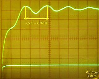 |
This is called a transient response of system. To refinement our fres we tune generator around this estimated fres (now we should have 50% duty cycle) and seeking for signal maximum.
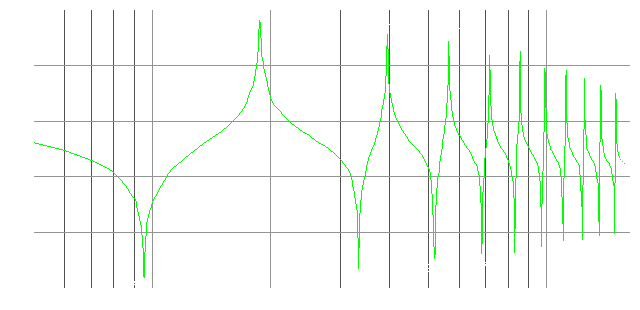
If we have a sine wave generator (I have only my terrible R-C Wienn bastle which is very unstable while tuning) we only need to tune frequency up from around 100 kHz (for small an middle TCs) and watch voltage on sense resistor (I used 100 kohm) on oscilloscope. The first voltage maximum matches our fres. If we tune to higher frequencies we surprisingly find other less strong maximums. This higher maximums are higher resonant modes, not harmonics. They are not integer multiples of basic (fundamental) resonating frequency fres. I try to explain their meaning at next drawing:

When TC is excited at higher resonant mode problems may occur. Turn-to-turn breakout may occured in voltage maximums when more power is fed to TC. Where is voltage maximum there is current minimum and where is voltage minimum there is current maximum. Current maximums may melt thin wire at higher input power. So it's recommended to check what is the current resonating mode before applying full power to new TC.
Then frequency response may looks like this (fres = 94,5 kHz; frequencies of higher modes are not integer multiples of fundamental frequency):
Till now we think over independent secondary coil. After we attach the primary coil it becomes much more complicated. There will arise two magnetically coupled resonant circuits. Some theory about resonant circuits is here and here. To simplify it we would expect the both fres are the same. Shape of the frequency response of its mutual impedance (Zt = U2/I1) is expressively affected by coupling factor k and quality factor Q. More accurately on value of k*Q expression. Coupling factor is a number from <0..1> range. Simple it says how much the change in 1st resonant circuit affects the 2nd resonant circuit. When k is great then coupling is more tight. We can estimate it from geometrical coils setup. When the windings are closely together and more turns of both winding overlays then the k is greater. For SSTC/VTTC is recommended to use tight coupling. But it's needed to beware flashovers. Q is quality factor of both resonant circuits, Q = sqrt(Q1*Q2) - geometrical average of partial quality factors. Q of parallel resonant circuit is generally determined by reactive component X and resistive (lossy) component R ratio. Most TCs reaches (unloaded) Q factor in range of 50 - 100. When k*Q<1, it's subcritical coupling. Frequency response has one flat maximum. When k*Q = 1, it's critical coupling. There is still one maximum but most sharp (lowest bandwidth). And when k*Q>1, it's supercritical coupling with two maximums on Zt curve and drop between:
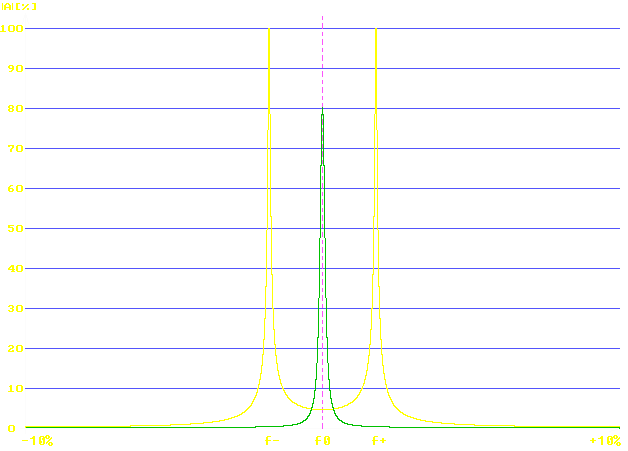
In my case I measured secondary coil fres at 333 kHz. According to measured primary inductance I chose capacitor's value to resonate at 333 kHz too. Then I measured it again (with generator connected to both primary coil terminals via resistor). I found two maximums at f- = 283 kHz and f+ = 410 kHz with anything between. From this two frequencies the k may be calculated by equation: k = (f0/f-)2 - 1 or k = 1 - (f0/f+)2. If both values differ it means that resonating circuits are not accurately tuned to the same frequency. I calculated k = 0,36. All this measurements I made with low level signals from generator. It may considerable change in real operation with high power inputs. Due to sparks and air ionization the strength of capacitive coupling to surroundings will change.
I found useful program MANDK from Mark S. Rzeszotarski on the Internet. It can calculate primary and secondary coils inductances, capacitances, fres, Q and coupling factor k depending on mechanical shift between primary and secondary coil. In my case the results are accurate pretty well. Attention! All dimensions must be entered in inches (1" = 2,54 cm).
It's seen that TC is a very complex device dependent on a lot of variables. Till now there's probably not discovered a perfect model which would describes all its effects. So I wait how TC will furthermore surprise me...
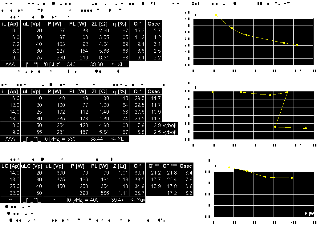
6.10.2005 As I wrote before in VTTC section, the impedance matching is very important. I made a bit more detailed measurement today. The goal is to get a rough idea how the impedance and Q-factor of TC depends on amount of sparks flashing from it's secondary.
The MANDK program calculates Q0 (of unloaded secondary) too high - about 110 for my BigTC. I measured Q ~ 60 using frequency generator and scope. That's because MANDK doesn't include dielectric losses in secondary form. But this is just beginning... Once sparks break out from secondary further Q-factor decrease will occur. We can imagine that discharge like a capacitive-resistive load connected between top of the secondary and ground. Capacitive component detune our secondary to lower frequency (discharge is conductive plasma, it has similar effect like placing a metal toroid on top). Resistive component damps the resonant circuit (most of energy in discharge turns to heat like in resistor) which cause lowering its impedance. Of course it's reflected on primary side and if impedance drops under value of output impedance of driving supply the power transfer to TC drops too. And the driver become overloaded by larger current (which we can see eg. like red glowing plate of vacuum tube or popping MOSFETs :).
From measured operational Q-factor we can simple calculate or estimate the optimal primary inductance and tank capacity to match the giver driver. If the driver have output impedance Ri it should equal to operational impedance on primary side of TC, Zpri = Ri. When tuned to resonance, XL = XC = Zpri/Q, now we can get the inductance and capacity from reactances. We are working with estimation so it's good idea to make a little bit more turns and some taps on primary and try it.
The measurement was done on my BigTC powered by SSTC IGBT halfbridge with filtered power Vdd supply (220 + 390 µF). The RF current was measured via two low-inductance 0,5 ohm resistors in parallel by my 2-channel scope Grundig MO 52. Incoming power of whole SSTC was measured by Metex multimeter M-3860M with TrueRMS. In tables are written peak values which I recalculated via shapes to RMS values for further calculations.
In 1st table the TC primary is connected directly to SSTC driver with spike on secondary. So discharge break out immediately, for whole measure (about 1,5 - 5 cm long).
In 2nd table is the same circuit but I placed a small metal ball on the spike. So discharge did break out later with more power. See the discontinuity in graph.
In 3rd table the TC primary is connected via serial resonant capacitor 12,3 nF / 4,5 kV as DRSSTC. On the secondary is only the spike so it sparks immediately:
24.12.2008 I made new secondary top design - I added new discharge terminal and toroid.