 |
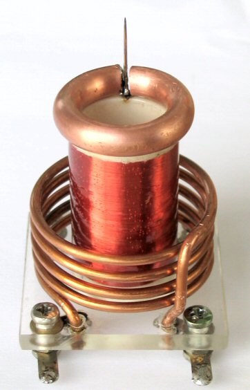
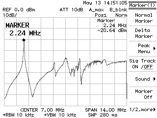
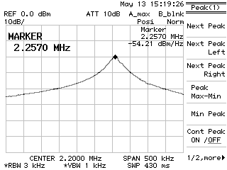
Resonant frequency was calculated around 3 MHz by MANDK program. Practically it is very affected by top terminal. It's around 2,6 MHz with needle spike only. If I put there a small glowing tube it drops at 2,4 MHz and with topload made of alufoil-wrapped tennis ball it drops even at 1,4 MHz. During tuning I found that Q-factor of resonator is quite low. It's probably due to high frequency combined with very thin wire. The DC resistance of those 32 m of thin wire is 330 ohms and it will be even bigger at high operating frequency due to skineffect. Later I tried to measure frequency response with spectrum analyser and wobbled RF generator (with mini-toroid on the top). You can see resonant peaks of higher modes. According to resonant curve bandwidth I guess the Q-factor (unloaded) to be aroud 60.
 |
 |
Now coming the question how to drive the microTC. My first idea was to use power double AND gate 75451 from TI in push-pull topology. It has open-collector outputs which can switch up to 400 mA at 30 V. Push-pull topology has one disadvantage-when driving signal dropped out (or before circuit become oscillating) one of two switches stays opened and huge DC current will flow through it. It can cause damage to it. I simple solve this with power 7,5ohm resistor connected between primary's center tap and power supply.

But this circuit didn't work well and blew up quickly. The most problem was high peak Uce voltage across open-collector outputs. With only 10 VDC supply voltage I got 30 V peak voltage. When I supplied it with 12 VDC the package of 75451 exploded. Before it happened I got about 5mm corona sparking out of needle's spike. It's interesting that output voltage of 75451 was not square but it looked like half-wave rectified sine wave. This may be the reason why the IC was heating-because it was not running fully in switching mode.
 |
 |
 |
 |
 |
18.8.2004 After failure of my first circuitry I tried to boost my push-pull with two power MOSFETs IRF630 (Udsmax = 200 V, Id = 9 A, Rdson = 0,4 Ω) driven by UCC2731/2 gate drivers. But this circuit didn't work well too. I was driving it from TTL generator instead antenna and when I was out of resonance there was nasty voltage peaks across the MOSFETs (several tens of volts when only 5 VDC supply used). When I tuned the generator both gate drivers suddenly blew but MOSFETs survived.
So I returned back to proof half-bridge topology.

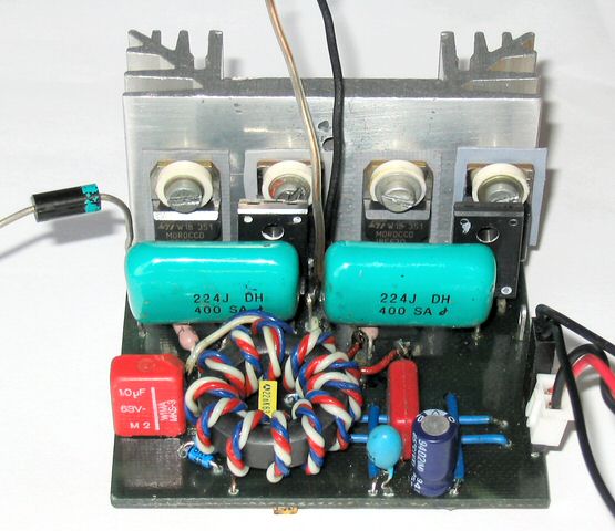
I use the IRF630 MOSFETs again especially due to relative low gate capacitance and fast switching times. There is classic diode network around them to disable slow internal body diodes. The GDT was wound trifillar with 7 turns on ferrite core from an old computer monitor. Maybe I unwound some turns because droop effect is noticeable till under 100 kHz. GDT is driven with pair of UCC27321/2D (inverting and non-inverting gatedriver) via DC blocking capacitor. I didn't take a care of deadtime control now so I accept greater losses in MOSFETs. I have done whole half-bridge circuit including PCB in about 4 hours. After I turned it on I was unpleasantly surprised by very heating gatedrivers. But I shouldn't wonder of that. One example from datasheet is describing calculation of maximum operating frequency for 10 nF load and they got 300 kHz. This mean that I cannot load it with more than 1 nF at 3 MHz. To prevent blowing of gatedrivers I had to lower the supply voltage to only 5 V (at 200 mA DC current draw) but this is only a few above MOSFET's treshold voltage. Half-bridge was able to operate from 12 VDC for a short time but it was heating a lot.
The first step I should do is to replace big 2W Zener-diodes with smaller ones because these have big capacitance (about 500 pF for serial combination). Then I would replace gatedrivers by UCC27321/2DGN with heatspreader plate on bottom side of package. And also I will play with GDT. Maybe I will buy some better ferrite core and rewound it.
11.9.2004 I have made some improvements on my halfbridge circuit:
1) Replacement of 20 V / 2 W Zener-diodes by 18 V / 0,5 W. Capacitance of the antiserial combination has decreased from 500 pF to 90 pF and this significantly unloaded gate driver ICs.
2) Replacement of gate drivers UCC27321/2D by UCC27321/2DGN. Theirs package are smaller but due to metal plate on bottom side they can dissipate 2-times more heat. So then I could increase supply voltage for the GDICs up to 8 V (eating 330 mA),where MOSFETs are reliable switching.
3) GDT was rewound on a new, last proof, ferrite core FT 82-43. Due to lower permeability I had to increase number of GDT turns. This improved gate voltage shape little bit.
4) 1ohm resistors were inserted serial to MOSFETs gates to damp oscillations of GDT.
5) External free-wheeling Schottky-diodes BAT48 was added on gate driver ICs outputs. This has not any effect but I left them there cause I'm lazy to solder them out.
After these modifications I made low voltage halfbridge test. The first visible sparks I got at 12 VDC. Sparks has oblong shape without any branching going up in same direction as needle spike. It was silent. Then I increased voltage to 16 VDC and 35 VDC / 1,6 A, where sparks became branched and hissing. Max. spark length was about 1,5 cm in to air. During that the halfbridge was heating. Then I tried supplying by half-wave rectified voltage up to 48 VAC where sparks was 2 - 2,5 cm. I had some flashover problems between secondary and very tight coupled primary (6 turns), so I rewound primary coil with greater diameter (5 turns). I also tried to add primary resonant 3,9nF capacitor in serial with primary but it didn't improve performance much. But when I was experimenting with adding a topload, instead a toroid I used metal starter for fluorescent lamps, I achieved significant sparks prolong up to 4,5 cm. It also lowered secondary resonant frequency to about 1,7 MHz.
Unfortunately I found out very unpleasantness thing - with only this little input power my secondary winding overheats very quickly. Probably due to high-resistance very thin wire I used. I found out this later, when visible deformations of varnished winding surface could be seen. There's only one way how to prevent overheating and keep good spark length - decrease average input power using low duty cycle. I'm thinking about to use ISSTC (Interrupted SSTC) idea. For this purpose I wired enable pin of both GDICs to input connector on halfbridge PCB. Let there be connected a TTL signal with given duty cycle and frequency from few Hz to kHz. So I'm curious how this helps.
 |
 |